What The (R)F(Test) Part 1
Posts In Series
This turned into a multi-post series, here's all the posts:
Under The Gun
Another day, another EMC testing session requiring a poorly documented test mode. If you've ever had the pleasure of being EMC firmware support, you'll know this usually involves vendor-supplied-blackbox firmware. There might be some minimal documentation hinting how to place your device into the special mode, if they're feeling generous. Thanks to some frantic searching, a few hunches, and luck, I figured out the correct incantation that day. Since Espressif's documentation was not very detailed, I had all the spiteful motivation I needed to document my efforts reverse engineering the command I used.
Test Modes
Test engineers usually look a continuous transmission mode at a particular channel for the band your device transmits in. In my case, we had a BLE pre-certified module which simplifies our product's testing. We still needed measurements in the worst case recorded by the module's original certification testing. In my case, this was:
- Continuous Transmission
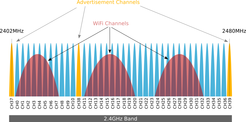
- On BLE channel 391
If you are not able to get your device into a mode like this, your test engineer should perform a duty cycle compensation for whatever transmission mode you can operate in. Again, I lucked out and figured out this command on the fly, but you might not be so lucky with your device. Come to the chamber prepared for these scenarios so you don't waste precious and costly testing time. Doesn't matter how nice the testing house is, they're gonna bill you and probably by the hour.
Saved by strings
The day of our test I downloaded Espressif's RF testing binaries2. These flashed just fine onto our device, but I had a real problem. I had no idea how to actually drive the firmware. My dev machine runs Linux3 and Espressif's application is Windows-only :-(. My attempts to install on my Windows machine led to failure thanks to some security configuration issues. I attempted to run it with various emulation layers (Wine, Bottles, etc.) but struck out on that front. The online docs had some info but clearly only supported Windows, Linux was out of the question. The docs packaged with the application + firmware were useless, but at least a little goofy. Single PDF pages in Chinese containing links to English documentation online... I guess that still counts as docs.
At this point, I turned towards reverse-engineering the app <-> firmware interface. My first idea was to see if the binary had any debug symbols, nope. Next I thought maybe I could glean enough info from the docs and hope that the firmware used a simple console for control. This hunch was right and the docs provided some example output to expect when running a test:
fcc_le_tx_syncw:txpwr=15,chan=0,len=250,data_type=0,syncw=0x71764129,rate=0,tx_num=0,contin_en=0,delay=0,hopp_en=0
With this hint, I turned to my trusty pals, strings and rg. Running strings <esp_rf_test_binary> | rg 'fcc_le_tx_syncw' yielded the results I was looking for. We had a text-based command console and this was the name of one command. After several tries experimenting with parameter values, we were up and running on ch 39 and passing our tests shortly after that.
Mission Accomplished?
While I was happy to be over that hump, I was still pretty frustrated that took that much effort! Espressif is no stranger to Linux support so it's a bummer that the companion app for this firmware is Windows-only. I also wasn't super confident that I had configured the command exactly as I wanted. It was sufficient for testing, but I had basically guessed and got lucky. I wanted more confidence and understanding what the setup was. I've built firmware and applications like this throughout my career, so my curiosity got the better of me: could I reverse engineer this firmware and learn more about what features it has? Maybe I could reverse engineer the app too and do a Linux port too!4
Ghidra Time
If you haven't gotten to use Ghidra5 before, I highly recommend giving it a spin. Ghidra is an open-source reverse engineering toolkit that I've used in the past to decompile code, investigate images for data and instructions, and search through bytes for patterns. I started by loading the Windows binary and running the default analyzers.
Windows Analysis, Attempt 1
I saw promise when the analyzers completed their runs. The program's entry point was decompiled, and I could trace through and learned a few things:
- The app was built using a Python-based GUI framework. To my knowledge this could have been tkinter or PyQt
- No signs of the command strings though. That was odd to me since I knew the primary interface was via the console and it was text-based
At this point, I was not making much progress and decided to turn my attention over to the firmware.
Firmware Analysis
First Pass
Repeating the same steps with the firmware binary did not yield great results at first. Ghidra does support the Xtensa architecture, but it doesn't really know much about the memory layout of ESP32 & co. After doing some research, I discovered there are a few additional components I could install on top of Ghidra to set things up with the ESP326. These additional steps add data sources from the ESP32 ROM ELF, and SVD files. We use the ROM because this contains a library that the application calls out to and also the first-stage bootloader. With these in place, I reloaded the binary and re-ran the analyzers.
Finding The Right Main
More signs of hope! Ghidra decompiled a lot of code which was pretty exciting! At the end of the analysis, Ghidra plopped me right at the main() it found. This was not the main() I was looking for. Ghidra had done it's job and found main()... but from the ROM. A quick command with nm esp32s3_rev0_rom.elf | rg main to spit out the address from the ROM and then navigating to 0x40043a2c in Ghidra confirmed this.
Still, this was progress. I next searched for the command string, fcc_tx_le, and found this within the firmware. But nothing appeared to reference the address directly which puzzled me. Thinking back to Ghidra dropping me at the ROM main(), I wondered if it even knew to analyze the application code regions. The ROM certainly has no clue about any command strings but the app must. Typically with ESP-IDF applications, there is a second-stage bootloader built along with the application. I kind of doubted this RF testing firmware was built in this manner. The second stage bootloader is there to handle booting the application, applying OTA operations, etc. None of that is needed with this scenario though. So maybe what we're dealing with is an RF test firmware built to be loaded by the ROM first-stage. I set off looking for a method to determine the entry point. Turns out, you can do this in many ways and Espressif documents this quite well. I turned to esp32knife7, a ESP32 utility for reverse-engineering. You can also use esptool (usually included in your ESP-IDF environment) directly, or take a look at the docs 8 and decode the image bytes yourself. For my case, here's what I ran:
# I used uv here, but you can use Python directly as well
$ uv run esp32knife.py --chip esp32s3 load_from_file ~/Downloads/EspRFTestTool_v4.7_Manual/Bin/RF_TEST_BIN/ESP32-S3_RFTest_V112_b7bc9b9_20240430.bin
Prepare output directories:
- removing old directory: parsed
- creating directory: parsed
Reading firmware from: /home/Downloads/EspRFTestTool_v4.7_Manual/Bin/RF_TEST_BIN/ESP32-S3_RFTest_V112_b7bc9b9_20240430.bin
Writing bootloader to: parsed/bootloader.bin
Bootloader image info:
=================================================================================
Image version: 1
Entry point: 4037a820
real partition size: 141728
flash_mode: 2
flash_size_freq: 0
2 segments

Segment 1 : len 0x04c80 load 0x3fcb0000 file_offs 0x00000018 BYTE_ACCESSIBLE,MEM_INTERNAL,DRAM
Segment 2 : len 0x1dccc load 0x40378000 file_offs 0x00004ca0 MEM_INTERNAL,IRAM
Checksum: 80 (valid)
Validation Hash: 632af6013dd594342d6f80a93cdd2bd80ea2138251ca580258b27e1f379f4c08 (valid)
Segment at addr=0x3fcb0000 => {'BYTE_ACCESSIBLE', 'DRAM', 'MEM_INTERNAL'} => .dram0.data
Segment at addr=0x40378000 => {'IRAM', 'MEM_INTERNAL'} => .iram0.text

Adding program headers
prg_seg 0 : 3fcb0000 00004c80 rw .dram0.data
prg_seg 1 : 40378000 0001dccc rwx .iram0.text
Program Headers:
Type  Offset    VirtAddr  PhysAddr  FileSize  MemSize  Flg Align
 1    00000167  3fcb0000  3fcb0000  00004c80  00004c80  6  1000
 1    00004de7  40378000  40378000  0001dccc  0001dccc  7  1000

Writing ELF to parsed/bootloader.bin.elf...
=================================================================================

No partition table found at: 8000
No partition table found at: 9000
Failed to find partitions table, exiting
note: You can see that esp32knife is expecting to find a partition table but can't. This points to firmware built to be loaded by the first-stage bootloader vs the second-stage bootloader.
Now I had the actual RF firmware main() at 0x4037a820. Next up was to explain to Ghidra that there was a function here! My next post will detail my efforts to dive into the application code.
https://docs.espressif.com/projects/esp-test-tools/en/latest/esp32s3/development_stage/rf_test_items/bt_ble_non_signaling_test.html#bluetooth-le-tx-performance-test
BLE has a quirky mapping between logical channels and frequency. Here's a handy link to a good diagram if you need to remember: https://people.eecs.berkeley.edu/~boser/courses/49_sp_2019/figures/comm/ble_channels.png↩
Despite this set back, it is still the Year Of The Linux Desktop↩
I have a now 8-month old, that's not happening any time soon lol↩